
Compex is an Italian brand of guide rails suitable for applications such as kitchen drawers, cabinet runners, and door/window tracks. In recent years, Europe and America have imported substantial quantities of guide rails, with significant demand for commercial stainless steel variants. Their manufacturing requires advanced technical expertise, as they must withstand diverse environments while offering corrosion resistance and high load-bearing capacity. Dimensions must be precise to the millimetre. Naturally, understanding guide rail installation is crucial.
I. Let us first examine the structural diagram of the guide rail, as shown below:
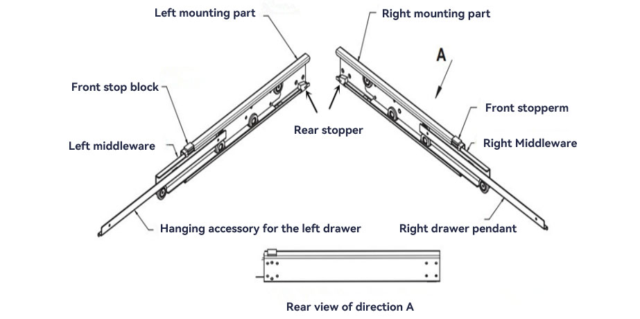
The guide rail comprises four major components: mounting brackets, intermediate connectors, installation fittings, front end stops, and rear end stops.
Product length: 300mm~~750mm
Total length (product length + running length): 590mm to 1490mm
Installation methods: Hook-type installation + Screw-type installation
II. Drawer Guide Rail Installation Diagram
Drawer Guide Rail Installation
First, select suitable guide rails based on the product design drawings to choose the most appropriate rail type
1. Install left and right drawer brackets:
a. Prior to bending the drawer, punch positioning holes (aligned with the two locating holes on the drawer bracket) to ensure the straight line of the locating holes on both sides remains parallel after bending.
b. After forming the drawer, measure each side length with a tape measure to check for bending tolerances. If the bending tolerance is excessive, the drawer should not be used.
c. Secure the drawer brackets using spot welding or full welding. Temporary adhesive fixing may be used initially. Once the smooth engagement between the bracket and guide rail has been verified, proceed with permanent welding.
2. When installing front and rear support columns, the front column should generally be fixed first, followed by adjustment of the rear column position.
2. Method:
Determine the lateral distance between front and rear support columns based on the drawer dimensions.
Determine the longitudinal distance between front and rear support posts based on the length of the main rail assembly.
Establish the horizontal distance for the front support post and secure it firmly with screws. The exact horizontal distance depends on the drawer’s horizontal dimensions, the thickness of the guide rail mounting bracket, intermediate bracket, and drawer hanging bracket. Next, fabricate a crossbeam equal in length to the front support column’s horizontal distance. This facilitates determining the rear support column’s horizontal distance while also securing the rear support column to prevent deformation caused by cabinet foam expansion.
b. Measure the distance between the front and rear spot-weld positions or hook locations on the guide rails. Use the fixed-width crossbeam to secure the installation position of the rear support column;
c. Secure the crossbeam to the rear support column and the rear support column to the cabinet using screws or other methods. This completes the installation of both front and rear support columns.
3. Installation Notes:
a. Hook-type guide rails: Supports feature hook holes. Support steel plate thickness is 1mm; generally, steel plate thickness should not exceed 2mm as hook hole width is approximately 2mm.
b. Screw-type guide rails: Do not require hook holes and impose no strict thickness requirements on steel plates.
4. Installing the Main Guide Rail Components
Insert the drawer, fitted with its left and right drawer hangers, into the sliding track to complete installation.
a. Hook-type guide rails: Hook the main guide rail assembly onto the front and rear support pillars. If the hooks prove difficult to install or prone to dislodgement, adjust the support pillar positions accordingly.
b. Screw-type guide rails: Secure the main guide rail components to the front and rear support columns using spot welding, arc welding, or screws.
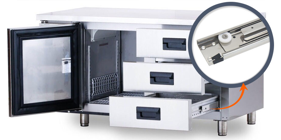
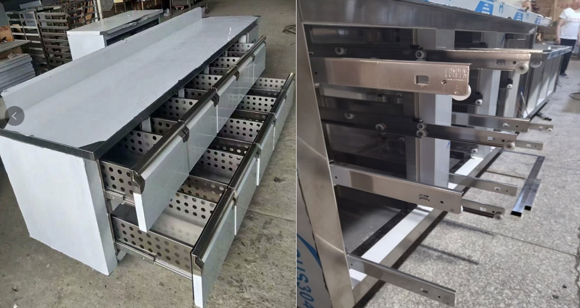
Actual installation diagram of guide rails for commercial refrigerators:
Upon completing slide installation, failure to observe proper techniques and details often leads to the following issues:
I. Causes of drawer slide jamming and excessive noise:
1. Non-parallel slide installation. Solution: Employ a spirit level to ensure parallel alignment of slides, resolving horizontal spacing discrepancies in both slides and mounting brackets.
2. Inconsistent horizontal spacing between runners and brackets.
Techniques may include:
a. Fixed-width steel plate channels b. L-shaped rear support angle iron + fixed-width rear support crossbeam
c. Spacers to adjust support column horizontal spacing
Key considerations:
a. Control drawer manufacturing tolerances, ensuring front-to-back horizontal spacing does not exceed 1mm
b. Avoid welding deformation of the bracket
c. Ensure sufficient weld points for full or spot welding
II. Unstable fixation, prone to detachment – verify whether the front stop block has been omitted.
When selecting drawer runners, the foremost consideration is the quality of the steel. It is important to recognise that a drawer’s load-bearing capacity is significantly influenced by the quality of the runner steel. Different drawer specifications require varying steel thicknesses. COMPEX runners employ imported 304 stainless steel, offering high precision and extended service life. All pulleys at disassembly points are crafted from nylon 6.6 material. The comfort of pulley operation is closely linked to their composition. Commonly available pulleys utilise steel balls or nylon, with nylon pulleys representing the superior option, operating silently during use. Furthermore, the quality of the pulleys can be tested by manually sliding the drawer to check for any resistance, noise, or rattling. The above information provides an introduction to the installation of COMPEX guide rails. We hope this content proves helpful when required.
Post time: Oct-16-2025 Views: